Opto 22 Mux Driver
The Opto 22 Mux Driver is designed to communicate with Opto22™ B1, B2, B4 and B5 brain boards. Communications to the brain boards can be via an RS485 serial link for B1 and B2 brain boards or the Pamux™ bus using an ISA bus adapter card for B4 and B5 brain boards
The addresses available for your I/O tags are configured within this driver tag. An address selection is available, but rather than being a dialog to be opened, it is a drop-down list within the I/O tag, showing all available addresses as configured within the driver.
Server List
Select (or create) a named server list.
Opto 22 Mux properties, Serial tab

Brain Board Address
The brain board address.
Board Type
Choices as shown.
Channel
Choices as indicated.
Port
Select the serial port tag used to access the physical Opto 22 device.
Retries
The number of times to retry a message before declaring an error.
Use only if the driver is connected to a device that uses a serial port or a UDP/IP port that is configured to be polled. When connected directly to a device using TCP/IP, this value should normally be set to 0 since TCP/IP is a guaranteed message delivery protocol.
For unreliable communications, such as radio, set to 3 or 4.
Hold
Select this to have I/O tags attached to the driver hold their last value in the event of a communication failure. If not selected, tags will have their value set to invalid on a communication failure.
Time-Out Limit
Set the receiver time-out limit in seconds or fractions of a second. This is the length of time that this driver should wait for a reply from the PLC or RTU.
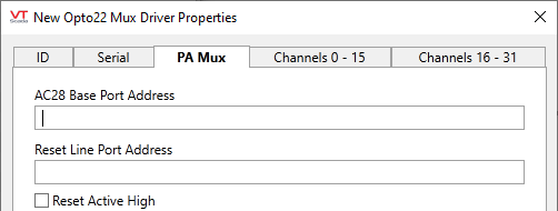
Opto 22 Mux properties, PA Mux tab

AC28 Base Port Address
AC28 adapter card base address. Only required for Pamux protocol
Reset Line Port Address
Port address for Pamux reset port. Only required for Pamux protocol.
Reset Active High
If set the brain board reset is active high. Only required for Pamux protocol.
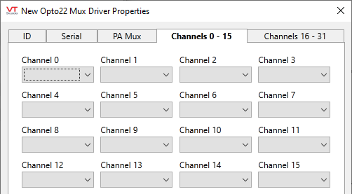
Opto 22 Mux properties, Channels 0 - 15 tab
This tab allows for the configuration of the individual channels of the Opto 22 device, 0 through 15.

Channel x:
This is configuration of the individual channels of the Opto 22 device. Options include:
- None = No module present
- DO = Digital Output
- DI = Digital Input
- AI = Analog Input
- AO = Analog Output
- ICTD = ICTD Probe AD4 Module
- RTD 10 = 10 Ohm RTD AD14T Module
- RTD 100 = 100 Ohm RTD AD10T Module
- TC-J = Type J Thermocouple AD5/AD5T Module
- TC-K = Type K Thermocouple AD8/AD8T Module
- TC-R = Type R Thermocouple AD17T Module
- TC-S = Type S Thermocouple AD17T Module
- TC-T = Type T Thermocouple AD18T Module
- TC-E = Type E Thermocouple AD19T Module
Opto 22 Mux properties, Channels 16 - 31 tab
This tab allows for the configuration of the individual channels of the Opto 22 device, 16 through 31.
Refer to the description of the previous tab for details.
