Not counted towards your tag license limit.
This tag is a DNP3 Master, which implements all the objects defined in DNP subset level 3, except for the "Frozen Counter" type. The driver does not generate "Freeze" requests, or class enable/disable messages. The driver supports a number of other objects as listed in a following topic.
Driver Errors: To learn more about the cause of an error condition, refer to the Driver Summary Report and the Driver Error Report, both of which are available in the Reports page. The Show Stats button will also provide current and last error messages: Show Statistics Button Widget
DNP3 drivers will commonly connect to TCP on port # 20000, although variations may be found.
Reference Notes:
DNP3 Drivers may be configured to accept in-bound connections from an RTU via a configured IP Network Listener tag. In DNP3 terms this is a 'dual-endpoint' where the IP network listener allows this to be a 'listening endpoint'.
This driver has the ability to save the last value written to each output tag, and to rewrite those values, either automatically when lost communications are restored, or manually by the press of a button. Carefully review the information in the Options tab to decide whether this feature should be used in your application.
If this driver is being used in conjunction with a Driver Multiplexer, then configure the Driver Multiplexer to store the last values, not the drivers connected to the Multiplexer. In this case, only the Multiplexer should be configured to re-write automatically.
As of VTScada version 12.1.39, drivers that do not have a suffix will use event-based polling. Refer to notes in DNP3DefaultNoScan and DNP3 I/O Addressing
The ID tab of every tag includes the same common elements: Name, Area, Description, and Help ID.
Name:
Uniquely identifies each tag in the application. If the tag is a child of another, the parent names will be displayed in a separate area before the name field.
You may right-click on the tag's name to add or remove a conditional start expression.
Area
The area field is used to group similar tags together. By defining an area, you make it possible to:
- Filter for particular tag groups when searching in the tag browser
- Link dial-out alarm rosters to Alarm tags having a particular area
- Limit the number of tags loaded upon startup.
- Filter the alarm display to show only certain areas.
- Filter tag selection by area when building reports
When working with Parent-Child tag structures, the area property of all child tags will automatically match the configured area of a parent. Naturally, you can change any tag's area as required. In the case of a child tag, the field background will turn yellow to indicate that you have applied an override. (Orange in the case of user-defined types. Refer to Configuration Field Colors)
To use the area field effectively, you might consider setting the same Area for each I/O driver and its related I/O tags to group all the tags representing the equipment processes installed at each I/O device. You might also consider naming the Area property for the physical location of the tag (i.e. a station or name of a landmark near the location of the I/O device). For serial port or Roster tags, you might configure the Area property according to the purpose of each tag, such as System or Communications.
You may define as many areas as you wish and you may leave the area blank for some tags (note that for Modem tags that are to be used with the Alarm Notification System, it is actually required that the area field be left blank).
To define a new area, type the name in the field. It will immediately be added. To use an existing area, use the drop-down list feature. Re-typing an existing area name is not recommended since a typo or misspelling will result in a second area being created.
There is no tool to remove an area name from VTScada since such a tool is unnecessary. An area definition will exist as long as any tag uses it and will stop existing when no tag uses it (following the next re-start).
Description
Tag names tend to be brief. The description field provides a way to give each tag a human-friendly note describing its purpose. While not mandatory, the description is highly recommended.
Tag descriptions are displayed in the tag browser, in the list of tags to be selected for a report and also on-screen when the operator holds the pointer over the tag’s widget. For installations that use the Alarm Notification System, the description will be spoken when identifying the tag that caused the alarm.
The description field will store up to 65,500 characters, but this will exceed the practical limits of what can be displayed on-screen.
This note is relevant only to those with a multilingual user interface:
When editing any textual parameter (description, area, engineering units...) always work in the phrase editor. Any changes made directly to the textual parameter will result in a new phrase being created rather than the existing phrase being changed.
In a unilingual application this makes no difference, but in a multilingual application it is regarded as poor practice.
Help Search Key
Used only by those who have created their own CHM-format context sensitive help files to accompany their application.
Server List
Select (or create) a named server list.
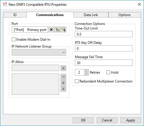
DNP3 Driver properties Communications tab
Contains driver communication parameters. If the configured port is using a modem for communications to a DNP3 outstation, this tag may be configured to accept incoming phone calls.
Note:
- The DNP3 broadcast addresses of 0xFFFD to 0xFFFF (65533 to 65535) are not supported in VTScada.
- Address 0xFFFC (65532) is reserved for the "Self-Address". This address is not supported in VTScada.
- Addresses 0xFFF0 to 0xFFFB (65520 to 65531) are DNP3 reserved addresses, which should not be used and therefore are not supported in VTScada.
- Removing these addresses from the pool gives the allowable range in VTScada of 0x0000 to 0xFFEF (0 to 65519).

Port
Enables you to select the Serial Port tag, TCP/IP tag or UDP/IP Port tag that you wish to be associated with this driver tag. A Serial Port tag opens a serial port to enable communications between VTScada and your PLC or RTU. A TCP/IP or UDP/IP tag enables you to connect to a series of hosts, allowing you to transmit data across a network or over the Internet. A port must be configured regardless of whether an IP Network Listener is also configured.
The Port field can be cleared using the X button that appears to its right.
Enable Modem Dial-In
Should be configured only if you expect the RTU to dial in using the VTScada Modem Manager. Do not use this option if an IP Network Listener is configured.
IP Network Listener Group
Configure only if this driver is to accept in-bound TCP or UDP communications. Select an existing IP Network Listener tag using the drop-down list. While a TCP connection is open, new connections will be rejected by the DNP3 driver.
If an IP Network Listener is configured, the Port tag must be a TCP/IP configured in client socket mode, or a UDP/IP tag.
IP Allow
Optional. Misconfiguration of this field is a common source of problems.
Used in connection with an IP Network Listener tag. General IP address filtering should be set on the IP Network Listener, as this will be more efficient. The list of allowed IP addresses in the driver is intended to prevent misconfigured devices from interfering with other devices.
Both filters (that in the Network Listener and this one) can be configured at the same time. The filter in the IP Network Listener will be applied when the device first connects and the local filter will be applied after a specific driver instance has been identified.
Time Out Limit
Sets the time in seconds or fractions of a second that this driver should wait for a reply from the remote unit.
RTS Key Off Delay
Sets the amount of time (in seconds) that this driver will wait before dropping RTS at the end of a data transmission.
Message Fail Time
The time interval for which VTScada will delay a failed message to allow other messages on the same port to be transmitted. This enables better performance when multiple RTUs share the same port and a message or messages to one RTU are timing out, thus slowing down communications to all RTUs. Usually set to 0 when there is only one driver using the port.
Retries
The number of times to retry a message before declaring an error.
Use only if the driver is connected to a device that uses a serial port or a UDP/IP port that is configured to be polled. When connected directly to a device using TCP/IP, this value should normally be set to 0 since TCP/IP is a guaranteed message delivery protocol.
For unreliable communications, such as radio, set to 3 or 4.
Hold
Select this to have I/O tags attached to the driver hold their last value in the event of a communication failure. If not selected, tags will have their value set to invalid on a communication failure.
Redundant Multiplexer Connection
This setting is incompatible with the DriverMUX's Parallel or Alternating modes.
Used only in the case that two DNP3 drivers will be subordinate to a Driver Multiplexer. If selected, this setting will prevent activity if the driver is a DriverMUX inactive subordinate.
When in this mode (option selected, current driver is the inactive subordinate driver) the DNP3 Driver will almost completely shut down except for periodic checking of its communications link.
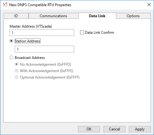
DNP3 Driver properties Data Link tab

Master Address (VTScada)
The station address for VTScada. This is the "from" address in messages from VTScada to the RTU, and the "to" address in messages from the RTU to VTScada. The range is 0 to 65519 ()xFFEF).
Station Address
The station address for the RTU. The valid range for this parameter is 0 to 65519.
If a broadcast address will be used, the station address is set automatically to 65533 (self-address).
Broadcast Address
The DNP3 driver supports 3 special outstation broadcast addresses that will allow an RTU that receives them to process the message. The 3 addresses are:
- 0xFFFD (65533) specifies that the outstation should not require confirmation for the broadcast received flag.
- 0xFFFE (65534) specifies that the outstation should require confirmation for the broadcast received flag.
- 0xFFFF (65535) specifies that the outstation may optionally require confirmation for the broadcast received flag.
Note that the use a broadcast address for a driver is of practical use only if the communications medium for that driver is also broadcast. For example, UDP to a broadcast address or Serial\TCP to a radio.
The only DNP3 objects that may be used by a driver employing a broadcast address are the Control Relay Output Block (CROB, g12v1) to set digital outputs and the Analog Output (g41v1-4) to set analog outputs.
As no replies are sent by outstations to the broadcast address, an instance of the driver using a broadcast address will never receive data.
An outstation that receives a broadcast message will indicate the fact in the Internal Indications value of a response, specifically the IINBroadcast flag. This is a publicly-accessible variable in each (non-broadcast) DNP3 driver instance that tracks the appropriate value in Outstation responses. Note that this value may be set for only a short period of time. Outstations may also generate events corresponding to the outputs set by broadcast, which will be reflected in I/O tags as per all other outputs.
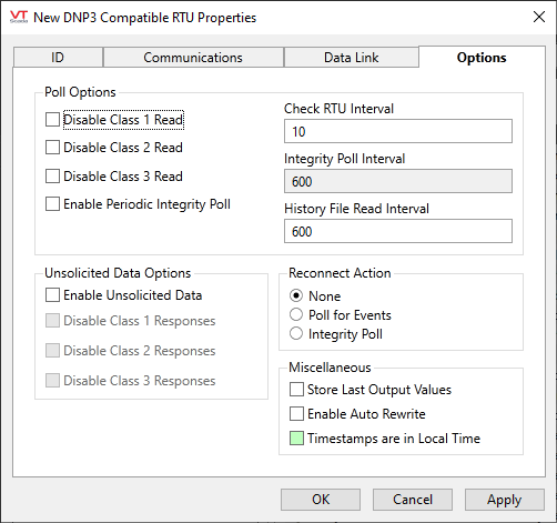
DNP3 Driver properties Options tab
Use the properties within this tab to fine-tune the driver behavior, adjusting it for your particular hardware.

Poll Options - Disable Class x Reads
Disable Class 1, 2 and 3 Reads. Any of these three DNP3 data classes may be disabled independently. A class marked as disabled will not be read, even if the outstation indicates that class data is available.
Check RTU Interval
The interval (in seconds) at which VTScada should check for class 1, 2 and 3 event data in the RTU. This function performs two tasks: checks that the outstation is still functioning and checks to see if the outstation has an event pending, which may be read. The outstation's configuration will determine which data changes are reported by events.
If your RTU is configured to spontaneously send values as they change (unsolicited data) you may choose to set the Check RTU Interval value to a relatively large value, thus minimizing bandwidth while still ensuring that values have been sent.
The interval is the time since the last check. For example, if set to 3600 at 12:00, the RTU will be checked and the next interval is now scheduled for 1:00. But, if any event causes a new check to happen at 12:45, the next interval will be 1:45.
Enable Periodic Integrity Poll & Integrity Poll Interval
This option may not be required.
When selected, VTScada will send a request for all values every Integrity Poll Interval seconds, even though these values may not have changed.
An Integrity Poll will read all enabled Class 1, 2, and 3 events (changes) then all Class 0 (current) values. Note that Class 0 values may not include all data types - this depends entirely on the configuration of the DNP3 device.
Regardless of whether the Enable Periodic Integrity Poll option is set, there are three situations when an integrity poll will always occur:
When the driver becomes the I/O server. When an RTU signals that is has re-started. When an RTU signals that event buffers have overflowed.
History File Read Interval
Refer to WITS History Reads. Sets the interval in seconds for History Reads. This overrides any interval set in the tags that are configured with a DNP3 WITS history address. The default value is 600s. Note that only history files using the WITS format are supported.
Unsolicited Data Options - Enable Unsolicited Data
The Enable Unsolicited Data option must be selected for VTScada to listen for unsolicited event messages (exceptions) from the RTU.
Disable Class x Responses
These options are available only when the Enable Unsolicited Data option has been set. Disable Class x Response to prevent the RTU from spontaneously sending event messages for that class. This affects only unsolicited messages from the RTU.
Reconnect Action
Choose what action to take when a connection to an RTU is re-established. The default action is "None" because the connection is usually re-established by VTScada making a Read request. No additional action is required in this case.
In rare circumstances an RTU may make the connection, then send no data. The Poll For Events option exists so that you can direct the DNP3 driver to send a request for changed data when this occurs.
In older (pre-10.0.12) versions of the driver, a reconnect would always cause an integrity poll to be done. The Integrity Poll option exists for legacy application support.
Store Last Output Values
When selected, the driver will maintain a record of the last value written to each output address. This may be useful in at least two situations:
- For hardware that does not maintain its state during a power loss and must be restored to that state when re-started.
- When failed hardware is replaced by a new device and you would like to start that device with the values last written to the old one.
If the last output values are stored, they may be re-written by either of two methods:
- Automatically, when communication is restored to the device.
- Manually by way of a button press. See, Rewrite Outputs Widget for details.
Changing this value from selected to deselected will cause all stored values to be erased immediately.
If this driver is being used in conjunction with a Driver Multiplexer, then configure the Driver Multiplexer to store the last values, not the drivers connected to the Multiplexer. In this case, only the Multiplexer should be configured to re-write automatically.
Enable Auto Rewrite
If selected, the Store Last Output Values option will also be activated. This option causes the driver to rewrite the last value written to each output, in the event that communications are lost and then restored.
Use this option only if you are certain that you want the last values to be rewritten automatically after an interruption in driver communications.
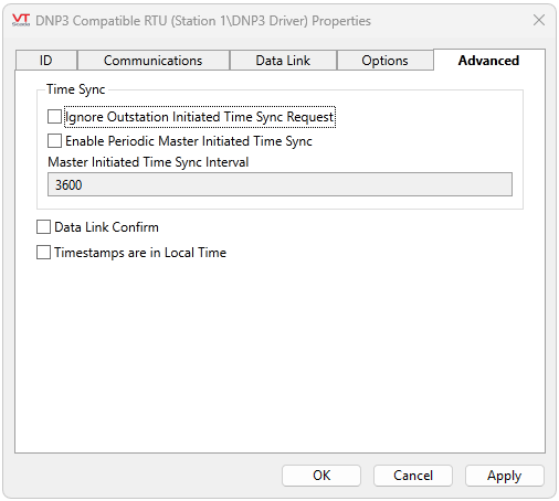
DNP3 Driver properties Advanced tab 
By default, the outstation requests time synchronization by setting the IIN1.4 "Time Synchronization Required" flag. The DNP3 driver responds by sending a time sync message to the outstation.

Time Sync - Ignore Outstation Initiated Time Sync Request
If enabled, the DNP3 driver will not respond to a time synchronization request from the outstation. (Defaults to FALSE)
Enable Periodic Master Initiated Time Sync
If enabled, the DNP3 driver will send the time synchronization message to the outstation after a period of time set in Master Initiated Time Sync Interval.
Master Initiated Time Sync Interval
If Enable Periodic Master Initiated Time Sync is enabled, this field indicates the time period in seconds. (Default 3600 seconds)
Data Link Confirm
If set, every low level data link message will be confirmed by an acknowledgment. This option is generally used in an environment where there are unreliable communications due to the extra non-data traffic sent.
Timestamps are in Local Time
Controls how the driver will send and interpret received timestamps from the RTU. If selected, then timestamps are in local time. If FALSE, then timestamps are in UTC. For most applications, UTC is the proper way to work with timestamps. The local option exists for compatibility with legacy applications.
The default for the parameter is controlled by the application property, DNP3LocalTimestampsDefault. Applications upgraded from versions before VTS 10 will default to '1', but new applications will default to '0' (UTC).
You are advised to leave this option unselected in order to avoid issues related to daylight savings time transitions.
The following widgets are available to display information about your application’s DNP3 driver tags:
