ScanCom Driver Tag
The ScanCom protocol is a derivation of the ADEPT protocol. It is used primarily to communicate with Barton Scanner devices.
The protocol is designed with 7-layers, for serial communication.
- ScanCom-7 Application
(VTScada in this case. Holds commands and responses) - ScanCom-6 Presentation
(ADEPT 4.0 only, contains measuring units – Imperial / Metric) - ScanCom-5 Session
(Similar to ScanCom-7 Application but applies to login / logout. A message can contain ScanCom-7 plus 6, or ScanCom-5 but not both) - ScanCom-4 Transport
(Used to break up large messages into multiple packets) - ScanCom-3 Network
(Not implemented) - ScanCom-2 Data Link Control
(Packet sequencing, CRC. Derived from another protocol called HDLC) - ScanCom-1 Physical
(Serial Port)
In VTScada, layers 5-7 are treated as a single-layer and layers 1 and 3 are ignored. The maximum packet size across layers 2 through 7 is 256 bytes.
Layers 3-7 use little-endian byte ordering but layer 2 uses big-endian byte ordering.
The ID tab of every tag includes the same common elements: Name, Area, Description, and Help ID.
Name:
Uniquely identifies each tag in the application. If the tag is a child of another, the parent names will be displayed in a separate area before the name field.
You may right-click on the tag's name to add or remove a conditional start expression.
Area
The area field is used to group similar tags together. By defining an area, you make it possible to:
- Filter for particular tag groups when searching in the tag browser
- Link dial-out alarm rosters to Alarm tags having a particular area
- Limit the number of tags loaded upon startup.
- Filter the alarm display to show only certain areas.
- Filter tag selection by area when building reports
When working with Parent-Child tag structures, the area property of all child tags will automatically match the configured area of a parent. Naturally, you can change any tag's area as required. In the case of a child tag, the field background will turn yellow to indicate that you have applied an override. (Orange in the case of user-defined types. Refer to Configuration Field Colors)
To use the area field effectively, you might consider setting the same Area for each I/O driver and its related I/O tags to group all the tags representing the equipment processes installed at each I/O device. You might also consider naming the Area property for the physical location of the tag (i.e. a station or name of a landmark near the location of the I/O device). For serial port or Roster tags, you might configure the Area property according to the purpose of each tag, such as System or Communications.
You may define as many areas as you wish and you may leave the area blank for some tags (note that for Modem tags that are to be used with the Alarm Notification System, it is actually required that the area field be left blank).
To define a new area, type the name in the field. It will immediately be added. To use an existing area, use the drop-down list feature. Re-typing an existing area name is not recommended since a typo or misspelling will result in a second area being created.
There is no tool to remove an area name from VTScada since such a tool is unnecessary. An area definition will exist as long as any tag uses it and will stop existing when no tag uses it (following the next re-start).
Description
Tag names tend to be brief. The description field provides a way to give each tag a human-friendly note describing its purpose. While not mandatory, the description is highly recommended.
Tag descriptions are displayed in the tag browser, in the list of tags to be selected for a report and also on-screen when the operator holds the pointer over the tag’s widget. For installations that use the Alarm Notification System, the description will be spoken when identifying the tag that caused the alarm.
The description field will store up to 65,500 characters, but this will exceed the practical limits of what can be displayed on-screen.
This note is relevant only to those with a multilingual user interface:
When editing any textual parameter (description, area, engineering units...) always work in the phrase editor. Any changes made directly to the textual parameter will result in a new phrase being created rather than the existing phrase being changed.
In a unilingual application this makes no difference, but in a multilingual application it is regarded as poor practice.
Help Search Key
Used only by those who have created their own CHM-format context sensitive help files to accompany their application.
Server List
Select (or create) a named server list.
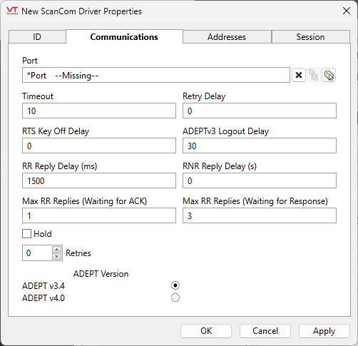
ScanCom Driver properties - Communications tab

Port
The ScanCom driver uses a serial protocol. If a serial port is not available on your server, use a Serial-to-Ethernet device with a TCP/IP port.
Timeout
The length of time (in seconds) that the driver should wait for a reply from the device. Defaults to 10 seconds.
Retry Delay
The Retry Delay field enables you to specify the amount of time (in seconds or fractions of a second) that the driver will wait between attempts to repeat a transmission of data if the previous attempt(s) have failed.
By default, the Retry Delay field is set to 0 (indicating that there should be no delay between retry attempts).
RTS Key Off Delay
The RTS Key Off Delay field represents the amount of time (in seconds) that this ScanCom driver will wait before dropping RTS at the end of a data transmission.
ADEPTv3 Logout Delay
Applies only when the ADEPT version is set to v3.4. Sets the delay (in seconds) the session will remain idle before automatically sending a logout message and ending the session.
(ADEPT v4.0 will always log you out automatically after a session ends and does not use this parameter.)
RR Reply Delay (ms)
The delay to wait after receiving a Receiver Ready acknowledgment before sending a Receiver Ready reply to the Scannner.
RNR Reply Delay (s)
The delay to wait after receiving a Receiver Not Ready acknowledgment before sending a Receiver Ready reply to the Scanner.
Max RR Replies (Waiting for ACK) and
Max RR Replies (Waiting for Response)
After sending a request to a device, several Receiver Ready messages may be exchanged while awaiting acknowledgment that the request was received (Waiting for ACK). Defaults to 1.
Similarly, several more may be exchanged while waiting for the reply (Waiting for Response). Defaults to 3.
These limits prevent an infinite number of such messages being exchanged. If the limits are exceeded error code 0x100C will be generated. If this error is generated frequently the Max RR Replies parameters should likely be increased.
Hold
Select this to have I/O tags attached to the driver hold their last value in the event of a communication failure. If not selected, tags will have their value set to invalid on a communication failure.
Retries
The number of times to retry a message before declaring an error.
Use only if the driver is connected to a device that uses a serial port or a UDP/IP port that is configured to be polled. When connected directly to a device using TCP/IP, this value should normally be set to 0 since TCP/IP is a guaranteed message delivery protocol.
For unreliable communications, such as radio, set to 3 or 4.
ADEPT Version
Specify 3.4 or 4.0 according to your device.
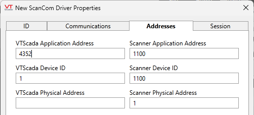
ScanCom Driver properties - Addresses tab

VTScada Application Address
The ADEPT-7 application address for VTScada. Defaults to 4352.
Scanner Application Address
The ADEPT-7 application address for the scanner. Defaults to 1100.
VTScada Device ID
The address at the ADEPT-4 Transport Layer for VTScada. Defaults to 1.
Scanner Device ID
The address at the ADEPT-4 Transport Layer for the scanner. Defaults to 1100.
VTScada Physical Address
The address at the ADEPT-4 Data Link Layer for VTScada. No default
Scanner Physical Address
The address at the ADEPT-4 Data Link Layer for the scanner. No default
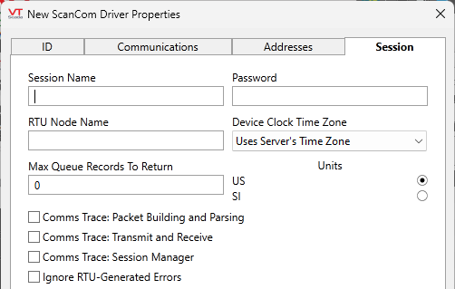
ScanCom Driver properties - Session tab

Session Name
Effectively, an encrypted version of the user name
Password
A password for the connection. The text will not be displayed. The password is stored in an encrypted form.
RTU Node Name
Upon a successful login request the Scanner will reply with its name as a text string. This field lets us ensure we are connected to the right Scanner.
Device Clock Time Zone
The default is to use the server's time zone. Select an alternative time zone if appropriate.
Max Queue Records to Return
The maximum number of queue records to be returned in a GETN response. A value of "0" means "no limit", or "send them all".
Units
Choose between US and SI.
Comms Trace: Packet Building and Parsing,
Comms Trace: Transmit and Receive,
Comms Trace: Session Manager,
These three parameters control what (if any) trace information should be logged. Look for the file in the folder Data\Trace Files of your application. The filename will take the form, <Name of Driver Tag>-YYYY-MM-DD.LOG For example: DemoScanCom-2023-06-08.LOG
Ignore RTU-Generated Errors
The Scanner provides return codes in its replies. By default the ScanCom Driver counts any non-zero return codes as driver errors, ending any operation in progress. This can be problematic in certain circumstances, such as if the Scanner returns an error code as part of a login transaction. For these occasions, the Ignore RTU-Generated Errors parameter allows us to disregard the Scanner return codes in order to connect to the device for diagnostic or corrective purposes. Note that the Scanner return codes provide important information, and this setting should not be enabled for extended periods of time.
The following widgets are available to display information about your ScanCom Driver tags:
ScanCom Driver Communication Messages Dialog
ScanCom Driver Statistics Dialog
