
Not counted towards your tag license limit.
The BSAP driver enables communications between VTScada and RTUs using the BSAP communication protocol.
The following property settings hold additional configuration parameters for your BSAP driver:
BSAPRestartTime - BSAP Driver restart time. Defaults to 15 seconds.
BSAPRBEScanRate - BSAP Driver RBE scan rate. Defaults to 300 seconds.
BSAPRBEScanSlice - BSAP Driver RBE scan slice. Defaults to 1.
BSAPRBEMsgFrmt - BSAP Driver RBE message format. Defaults to 1.
BSAPRBEStopXmit - BSAP Driver RBE Stop Transmit setting. Defaults to 0.
BSAPRBEWaitMsgTO - BSAP Driver RBE wait message timeout. Defaults to 300 seconds.
BSAPMaxFrameSize - BSAP Driver IBP maximum frame size. Defaults to 1000 bytes.
BSAPMsgSendTimeOut - BSAP Driver IBP message send timeout. Defaults to 0.5 seconds.
BSAPUnAckMsgCount - BSAP Driver IBP unacknowledged message count. Defaults to 15.
BSAPTimeSyncTimeOut - BSAP Driver time synch timeout. Defaults to 60 seconds.
BSAPUDPRetryDelay - BSAP Driver UDP retry delay. Defaults to 10 seconds.
The ID tab of every tag includes the same common elements: Name, Area, Description, and Help ID.
Name:
Uniquely identifies each tag in the application. If the tag is a child of another, the parent names will be displayed in a separate area before the name field.
You may right-click on the tag's name to add or remove a conditional start expression.
Area
The area field is used to group similar tags together. By defining an area, you make it possible to:
- Filter for particular tag groups when searching in the tag browser.
- Link dial-out alarm rosters to Alarm tags having a particular area.
- Limit the number of tags loaded upon startup.
- Filter the alarm display to show only certain areas.
- Filter tag selection by area when building reports.
When working with Parent-Child tag structures, the area property of all child tags will automatically match the configured area of a parent. Naturally, you can change any tag's area as required. In the case of a child tag, the field background will turn yellow to indicate that you have applied an override. (Orange in the case of user-defined types. Refer to Configuration Field Colors).
To use the area field effectively, you might consider setting the same Area for each I/O driver and its related I/O tags to group all the tags representing the equipment processes installed at each I/O device. You might also consider naming the Area property for the physical location of the tag (i.e. a station or name of a landmark near the location of the I/O device). For serial port or Roster tags, you might configure the Area property according to the purpose of each tag, such as System or Communications.
You may define as many areas as you wish and you may leave the area blank for some tags (note that for Modem tags that are to be used with the Alarm Notification System, it is actually required that the area field be left blank).
To define a new area, type the name in the field. It will immediately be added. To use an existing area, use the drop-down list feature. Re-typing an existing area name is not recommended since a typo or misspelling will result in a second area being created.
There is no tool to remove an area name from VTScada since such a tool is unnecessary. An area definition will exist as long as any tag uses it and will stop existing when no tag uses it (following the next re-start).
Description
Tag names tend to be brief. The description field provides a way to give each tag a human-friendly note describing its purpose. While not mandatory, the description is highly recommended.
Tag descriptions are displayed in the tag browser, in the list of tags to be selected for a report and also on-screen when the operator holds the pointer over the tag’s widget. For installations that use the Alarm Notification System, the description will be spoken when identifying the tag that caused the alarm.
The description field will store up to 65,500 characters, but this will exceed the practical limits of what can be displayed on-screen.
This note is relevant only to those with a multilingual user interface:
When editing any textual parameter (description, area, engineering units...) always work in the phrase editor. Any changes made directly to the textual parameter will result in a new phrase being created rather than the existing phrase being changed.
In a unilingual application this makes no difference, but in a multilingual application it is regarded as poor practice.
Help Search Key
Used only by those who have created their own CHM-format context sensitive help files to accompany their application.
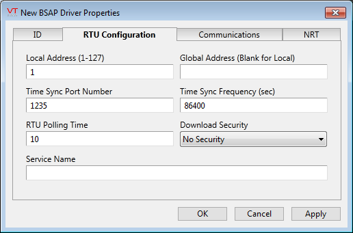
Local Address
Local address of level 0 RTU (1 - 127).
Global Address
Global address of the level 1 - 7 RTU - must be invalid for level 0 RTU
Time Sync Port Number
Time synchronization UDP port number.
Time Sync Frequency
Time synchronization frequency in seconds.
RTU Polling Time
Period between subsequent polls by the BSAP network manager of the level 0 RTU which may have other reachable RTU's via radio or other means. Note that the Network Manager communicates on a given port and all RTU's using that port use the same network Manager. Therefore if an RTU tag changes this value it will be updated in all the RTU drivers associated with that port. This is so that on a restart of the Network Manager, which can be started by a different driver tag, the driver would see the changed value.
Download Security
Used to attach a security privilege to the download functions on the driver. The user must have this privilege in their VTScada account to perform download functions.
Driver Service Name
The RPC service name to be used by this driver. Leave blank if unsure of using the same service as all other BSAP drivers.
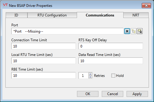
Connection Time Limit
Connection timeout for the network manager making a connection to a level 0 RTU. Note that the Network Manager communicates on a given port and all RTU's using that port use the same network Manager. Therefore if an RTU tag changes this value it will be updated in all the RTU drivers associated with that port. This is so that on a restart of the Network Manager, which can be started by a different driver tag, the driver would see the changed value.
RTS Key Off Delay
Key off delay for radio operation.
Local RTU Time Limit
Response timeout limit for level 0 RTU.
Data Read Time Limit
Read response time out limit for RTU response.
RBE Time Limit
Timeout limit to wait for a response for status request message from the RBE manager task in the RTU
Retries
Number of driver retries on failure before an error is logged. Note that the Network Manager communicates on a given port and all RTU's using that port use the same network Manager. Therefore if an RTU tag changes this value it will be updated in all the RTU drivers associated with that port. This is so that on a restart of the Network Manager, which can be started by a different driver tag, the driver would see the changed value.
Hold
If selected driver data will remain at the last known value on communications failure. If unselected data will be blanked or made Invalid.
The configuration of a BSAP driver's node routing table:
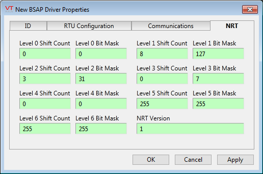
Global Address Calculation
A Network 3000 node determines its global address and its UP/DOWN mask as follows.
The calculation uses the node's local address, level number, level shift count, level bit mask and the global address of the node's local master. The NRT![]() Node Routing Table trickles down from the network master to all nodes on the net-work. A master passes an exact copy of its NRT to each of its slaves. Each slave then uses the procedure described following to construct its NRT which it then passes to each of its slaves. Both the NRT global ad-dress field and UP/DOWN mask starts off as zero (i.e. the network master's global address and UP/DOWN mask are by definition zero). As the NRT is distributed each node determines its global address and UP/DOWN mask and fills in the appropriate field in the NRT. Therefore the global address of a node is the concatenation of the local addresses of all previous local masters that the NRT has traveled to, from the network master to that node.
Node Routing Table trickles down from the network master to all nodes on the net-work. A master passes an exact copy of its NRT to each of its slaves. Each slave then uses the procedure described following to construct its NRT which it then passes to each of its slaves. Both the NRT global ad-dress field and UP/DOWN mask starts off as zero (i.e. the network master's global address and UP/DOWN mask are by definition zero). As the NRT is distributed each node determines its global address and UP/DOWN mask and fills in the appropriate field in the NRT. Therefore the global address of a node is the concatenation of the local addresses of all previous local masters that the NRT has traveled to, from the network master to that node.
The following steps illustrate the calculation of a node's global address.
- Increment level number
- Node's local address shifted left Level_Shift_Count times
- Result from step 1 is OR'ed in with the current NRT Global address (i.e. local master's global address)
- Result from step 2 is now placed in the NRT Global address field (i.e. now it is the node's global address)
The following steps illustrate the calculation of a node's UP/DOWN mask.
- Node's Level_Bit_Mask shifted left Level_Shift_Count times
- Result from step 1 is OR'ed in with the current NRT UP/DOWN mask (i.e. local master's UP/DOWN mask).
- Result from step 2 is now placed in the NRT UP/DOWN mask field (i.e. now it is the node's UP/DOWN mask).
The following widgets are available to display information about your BSAP driver tags:
BSAP Driver Addressing
The I/O tag addressing consists of a text-based tag name with a prefix as follows:
I/O Reads:
| I/O Read Prefix | Function |
|---|---|
| RDB | Read Database |
| PTP | Point to Point |
| RBE | Report by Exception |
I/O Writes:
| I/O Write Prefix | Function |
|---|---|
| DIG | Digital I/O Tags |
| ANA | Analog I/O Tags |
| STR | String I/O Tags |
