Used by: I/O and Calculations, Analog Input, Analog Output, Analog Status, Analog Control
* Does not use the Style Settings tag.
The Rotary Control enables operators to select a value to write to hardware by turning a knob. This is done by clicking on, then dragging the control clockwise or counter-clockwise. The value that will be set is shown in a tooltip while dragging.

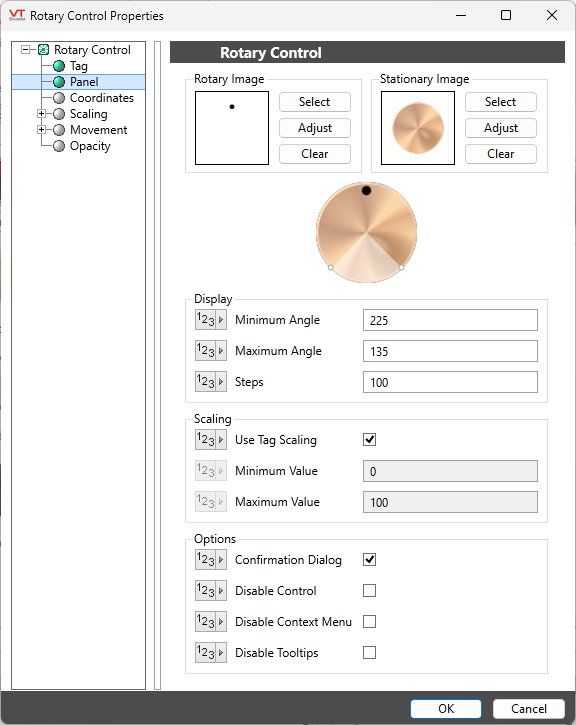
Properties dialog for the Rotary Control:

Rotary Image
The image that simulates the knob motion by rotating in response to the operator action. Usually a dot or bar that indicates the current position.
If creating your own image, it must be transparent other than the position indicator, which must be directly above the center of the image:

Image Select
Opens the Select Image dialog, within which you can browse for images, import new images, and select the image to use.
* VTScada recognizes the following image formats: .BMP, .CUT, .PCX, .EMF, .WMF, .JPG, .PNG, .TIF
Image Adjust
Opens the Adjust Image dialog box, which can be used to change the color and other display characteristics of the image. See: Adjust Image Dialog
Image Clear
Remove the selected image and do not select a replacement.
Stationary Image
The background image, providing context for the rotary image.
Minimum Angle / Maximum Angle
Limit the angle through which the control can rotate. In both cases, the angle is measured clockwise from vertical in units of degrees.
Steps
Sets the precision of the control, relative to the scaling value. The default value enables the operator to select 100 possible values within the scale range. This may not be appropriate for all controls.
Scaling
Choose whether to use the tag's minimum and maximum scaling values or to set alternative scaling values that will be applied to the output value.
Options
Confirmation Dialog / Disable Control / Disable Context Menu / Disable Tooltips.
Refer to Operator Interaction Controls for a full description of these standard widget options.
Analog Controls\
