POC-Lufkin SAM Well Manager
The POC-Lufkin SAM Well Manager is one of four pump-off controllers.
The Pump-Off Controller (POC) tags are designed as a single parent tag that will allow you to completely control and monitor a pump-off controller device. They contain drivers that have been pre-configured with the addresses and poll sequences necessary for reading Dynacard data, setpoints and other telemetry values.
The ID tab of every tag includes the same common elements: Name, Area, Description, and Help ID.
In a POC tag, the Name + Description parameters are used to identify the location of the well.
The Area + Alarm Notification Area parameters are used for grouping, filtering, and roster control
Name & Description
Together, these parameters define a unique identifier for the equipment. In some jurisdictions, the description is typically set to the LSD![]() Legal Subdivision address. or UWI
Legal Subdivision address. or UWI![]() Unique Well Identifier coordinates, but you are free to use whatever value makes sense for your system.
Unique Well Identifier coordinates, but you are free to use whatever value makes sense for your system.
Area & Alarm Notification Area
The area parameter is used to group similar tags together, such as all wells within a given region. An Alarm Notification Area can be defined so that separate rosters can be defined within one region, or so that wells from several fields can use one roster.
The Alarm Notification Area property is inherited by several of the Polling Driver children of this tag and then by any I/O or alarms below those. Child tags that are not expected to generate alarms will inherit the Area property.
If no Alarm Notification Area property is defined, all child tags will default to the Area property.
Help Search Key
Used only by those who have created their own CHM-format context sensitive help files to accompany their application. Refer to Custom Help Files
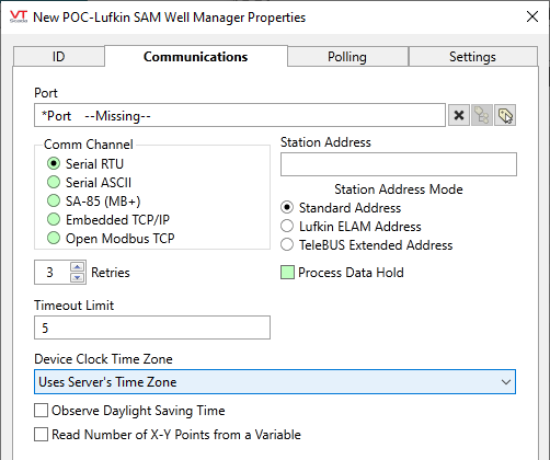
POC-Lufkin SAM Well Manager properties Communications tab

Port
Select the port tag, through which VTScada will communicate with this device.
Comm Channel
Select the communication channel and protocol to use for this Modbus Compatible Device driver. This will be one of:
- Serial RTU Select to use the RTU mode of the Modbus serial communications standard.
- Serial ASCII Select to use the ASCII mode of the Modbus serial communications standard.
- SA-85 (MB+) Select to use the Modbus Plus communications protocol via a Modicon SA-85 card.
- Embedded TCP/IP Select to use the Embedded TCP/IP protocol.
- Open Modbus TCP Select to use the Modicon Open Modbus/TCP specification to receive Modbus protocol over Ethernet TCP/IP.
Station Address
The station address of the Modicon programmable logic controller. By default, the PLC Address field is set to 1.
An expression may be used to provide the address if needed. This may be required on a network where the address varies depending on the workstation where the tag is running.
Note that, to create a valid expression for an address that contains non-numeric characters, you must enclose the address in quotation marks. e.g. "31.0.0.0" See: Modbus Plus PLC Addressing.
Station Address Mode
Use to limit the range of allowed addresses. Select according to your hardware.
Should only be adjusted if the Flow Computer/POC has been configured to use one of the specific addressing modes.
Standard Address ... 1 - 255 according to Modbus Protocol. Extended addressing ranges are not supported.
Lufkin ELAM Address ... 1 - 2295
TeleBUS Extended Address ... 1 - 65534
Time-Out Limit
Set the receiver time-out limit in seconds or fractions of a second. This is the length of time that this driver should wait for a reply from the PLC or RTU.
Retries
The number of times to retry a message before declaring an error.
Use only if the driver is connected to a device that uses a serial port or a UDP/IP port that is configured to be polled. When connected directly to a device using TCP/IP, this value should normally be set to 0 since TCP/IP is a guaranteed message delivery protocol.
For unreliable communications, such as radio, set to 3 or 4.
Hold
Select this to have I/O tags attached to the driver hold their last value in the event of a communication failure. If not selected, tags will have their value set to invalid on a communication failure.
Device Clock Time Zone
Select the time zone that the device uses in order to convert the time-stamped data from the device into UTC for storage in the VTScada historian. Regardless of the time zone selected with this option, the driver assumes that the device does NOT adjust its clock for daylight savings time (DST).
Defaults to the server's time zone, but may be set to use the device's clock if that is configured for UTC, otherwise any time zone where the device is located.
Observe Daylight Saving Time
Select if the RTU clock adjusts itself for Daylight Savings Time. Note that this does not necessarily mean that the RTU is in daylight savings time when this is being set. That is determined by the Windows operating system based on the selected time zone.
Read Number of X-Y Points from a Variable
Data is read from a set number of registers. Other information is read at the same time, including a “NumPoints” variable. This states how many of the registers contain actual data.
If the “Read Number of X-Y Points from a Variable” box is selected, VTScada will discard all of the extra registers beyond the number stated in NumPoints before passing the read results back to the Dynacard_Input tags. (See also: Dynacard Upload Driver Tag)
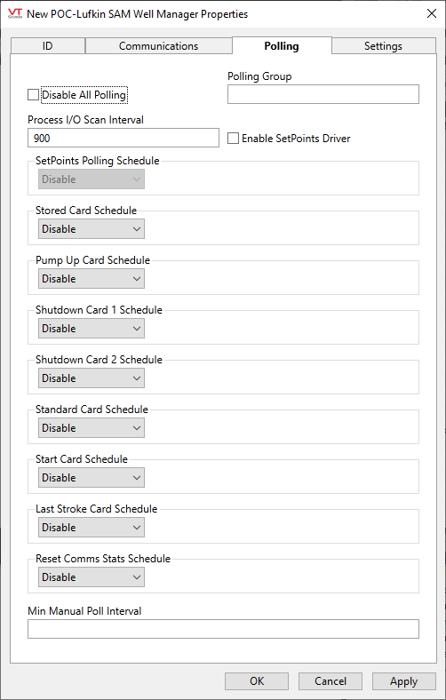
POC-Lufkin SAM Well Manager properties Polling tab

Disable All Polling
Select if communications are to be disabled at this site.
Polling Group
Provide a group name that will be used by the polling drivers within this tag. Groups ensure that polling drivers sharing a connection do not all try to poll at the same time. Each child Polling Driver will have its own sequence number within the group.
Useful only when two or more schedules match.
Process I/O Scan Interval
Measured in seconds, this sets the frequency at which process data is read.
Enable Setpoints Driver
If selected, tags in the \Process\Setpoints context will be polled using a dedicated setpoints driver instead of using the standard process driver. This allows the setpoints to be polled at a different rate from the other data.
Schedule Settings
Each polling schedule, when enabled, will offer a choice of "Hourly at", Daily, "Weekly on", or "Monthly on".
In each case, additional selections will be available, relevant to the overall scheduling of the poll.

Min Manual Poll Interval
Sets a minimum time between manual polls.
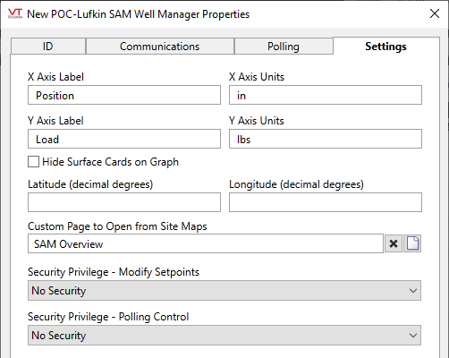
POC-Lufkin SAM Well Manager properties Settings tab

Labels and Units, X-Axis & Y-Axis
These are pre-configured with standard values, but you are free to provide your own labels and units to describe your system.
Hide Surface Cards on Graph
When selected, surface cards will not be shown.
Latitude and Longitude
Configure with the controller's location in order to display this site on a map.
Custom Page to Open from Site Maps
By default, the built-in SAM Overview page will open in response to an operator clicking on a site icon. You may create your own page, to use instead. Note that your custom page must be parameterized, taking a POC tag as its parameter.
Before selecting security privileges, you must first create those custom privileges. See: Protect Pages and Output Tags
Security Privilege - Modify Setpoints
Select the custom security privilege that you created in order to protect setpoints within this device.
Security Privilege - Polling Control
Select the custom security privilege that you created in order to protect polling control within this device.
The following widgets are available to display information about your tags:
Active Indicator
Data Age
Generic Driver Statistic
Polling Indicator
Dynacard Page Button
Dynacard Page Hotbox
Generic Driver Statistic
POC Manual Process Poll
POC Reset Comm Counts
Dynacard Display
Site Alarm List
Tag List
Site Icon
Alarm list
Draw HDV
